Dr Isaac Rosen, Senior Scientific Researcher at Copprint
Contact us info@copprint.com
Visit our virtual booth
My name is Isaac Rosen, and I lead an R&D team at Copprint where we work on the development of future products as well as solving customer challenges. I am responsible for our activities to create a process for soldering on conductive traces.
Electrical component assembly on printed electronics is primarily achieved today with ECAs, a strike difference from the practice in traditional electronics manufacturing where soldering is standard. This difference arises mainly from the difficulties in soldering on printed silver traces. Copprint pastes are copper-based, enabling excellent electrical properties that outperform silver pastes – higher conductivity and lower cost. It is possible to solder on traces formed with Copprint paste using standard off-the-shelf solder pastes. Strong solder bonds are formed with small resistors soldered on FR4, with up to 4 kgf needed to disconnect (via die shear force measurements).

Figure 1: Copprint copper paste, PCB with soldered components. Visit our virtual booth.
Copprint develops and manufactures conductive copper paste for various applications, including PCB board printing, membrane switches, RFID tags, and PV cells. We have copper pastes suitable for multiple substrates such as FR4, Paper, Glass, PI, PET, and more. Copprints product portfolio can be found here, including links inside for TDS, MSDS, application notes, and how-to videos. Copprint pastes can be used to replace silver pastes (expensive and toxic) as well as to replace polluting etching processes.
A key requirement for electronic manufacturing is component attachment to a printed circuit board. So far, when using silver pastes for printed electronics, good solderability with conventional solder pastes was difficult to obtain. The primary reason for the problem is that an IMC layer (Intermetallic Compound) cannot form between Tin, the main component in solder pastes, and silver metal. Therefore, manufacturers needing to attach components refrain from soldering and mainly use silver-based ECAs. Such ECAs are far more expensive than solder pastes (Silver vs. Tin prices) and far less standard in the PCB industries.
With Copprint pastes printed on FR4, we identified several compatible solder pastes, enabling the formation of a strong solder bond, with a proper IMC connection between the solder and the copper. The method advised (by solder paste manufacturers) for screening solder pastes was to visually look at wetting of the solder paste on the printed Cu surface after reflowing. The theory was that no wetting or de-wetting is a sign that the solder paste is not compatible. We learned from careful experimentation that wetting is not always the proper indication for compatibility and the potential to form a good soldered bond. In fact, this approach gave many false negatives.
A much better approach is to test the actual performance (formation of a strong soldered bond) of different solder pastes by soldering small (1206) chips to screen printed copper traces and measuring the die shear force needed to detach the chip.

Figure 2: Video showing applying solder paste, placing components, and soldering on printed copper traces in a reflow oven. Visit our virtual booth.
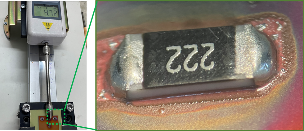
First, Copprint paste is screen printed on the substrate, followed by drying and sintering to obtain a conductive copper pattern (video). Then solder paste is applied with stencil printing, components are placed and soldered by reflow (the process in which the solder paste is heated, melts, and re-solidifies to form the bond) - See figure 2. Finally the soldered bond strength is tested as can be seen in Figure 3.

Figure 3: Photo of Die shear force test on 1206 SMD resistor chips soldered with SAC305 KOKI 955LV.
Using this approach, we found Compatible solder pastes that work well: form a strong bond that is hard to detach, requiring applying over 3kgf pressure to cause failure and detachment of the soldered chip. Non-compatible solder pastes do not work well: no solder bond is formed, and the chips can be detached with a gentle push. Furthermore, we found that for compatible solder pastes, the failure mode was detachment between the Cu and the substrate, while with non-compatible pastes, the failure mode was between the solder paste and the printed Cu surface. In addition, only with compatible pastes, an IMC layer was formed between the solder and the printed copper layer, which is the fundamental proof of the formation of a solder bond (figure 4).

Figure 4: Cross-section of solder bond, 1206 SMD LED soldered with SAC305 on Cu printed on FR4 substrate, micrograph on the right shows the presence of IMC. Visit our virtual booth.
The reason only some tested solder pastes were compatible is probably due to the flux system in each paste. Some fluxes work on the surface of copper patterns made with our copper paste, and some do not. As the fluxs formulation in the tested solder pastes are unknown (trade secrets), empirical testing is needed to approve a solder paste as compatible.
After establishing a good procedure for identifying compatible solder pastes, we tested a wide range of SAC305 and SnPb solder pastes on FR4, as well as SnBi and SnBiAg solder pastes on PET, resulting in a list of approved solder pastes, which can be supplied on request (info@copprint.com). Die shear forces above 2kgf were obtained with specific pastes from Henkel, Koki, AIM, Shenmao, Balvar Zinn and more. A very interesting and valuable finding is that soldering can be done on the printed copper traces without any post-processing. Even after few weeks of standard storage, a good die sheer force was achieved.
PET is an important substrate in printed electronics due to its low price, availability and durability. However, its low melting point does not enable the use of SAC or SnPb solder pastes. Compatible SnBi based solder pastes were identified, enabling a die shear force above 2 kgf on 125 um PET Details and recommended reflow profiles can be supplied on request via info@copprint.com.
To conclude, a simple soldering process for reliably connecting components on printed electronics was demonstrated. We expect faster adoption of printed electronics as component placement is more standard than the existing ECA method. This will happen with a transition from silver to copper for printing PCBs made on standard substrates like FR4 and newer substrates like PET.


Comments